The Data Link and Physical Layers
We will meander our way through both the data link and physical layers here, jumping back and forth between the two. While the network layer is concerned with how to route things so they eventually get to their destination, the data link and physical layers are concerned with the actual details of transferring data from one machine to the next. At this layer, the stuff being sent over the network is broken up into chunks called frames. At layer 4 the chunks are called segments, at layer 3 they are called packets, and here they are called frames.
Some basic concepts
| kilobits/sec (Kbps) | 1000 bits/sec |
| megabits/sec (Mbps) | 1 million bits/sec |
| gigabits/sec (Gbps) | 1 billion bits/sec |
A related term is throughput, which measures the actual amount of stuff that can get through in a given amount of time. Bandwidth is more like the theoretical maximum amount that can get through, but various issues usually keep you from maxing things out.
- Propagation delay — Nothing can travel faster than the speed of light, which is around 186,000 miles per second. For instance, it's about 2800 miles from Emmitsburg to San Francisco. Since 2800/186000 = .015 seconds, or 15 milliseconds. It is physically impossible to get information from Emmitsburg to San Francisco any faster than this. In fact, that 186,000 miles per second is the speed of light in a vacuum, like when it travels through space. In wires or through the atmosphere, we usually only get to maybe about 2/3 of that. Propagation delay can be as low as .001 microseconds (a nanosecond) when data has to travel 1 foot. If you're sending data across the solar system, it can be minutes or even hours long. For most network communications, it ranges from a few microseconds to a few milliseconds.
- Processing delay — Routers have to spend some time reading packets, processing headers, computing checksums, and deciding where to forward the packet. This usually takes a few microseconds.
- Queueing delay — When a packet reaches a router, chances are the router may be busy processing another packet, so it will have to wait. It's placed in a queue, with other packets possibly waiting ahead of it. The time it has to wait before being processed is the queueing delay. Depending on how busy the router is, this can range anywhere from microseconds to milliseconds.
- Transmission delay — A packet has a certain size, and all of the bits of the packet are not put onto the line at the exact same time. Think about the bits being put on in a row, one after another. The transmission delay is the time it takes to put all of the bits on the line. There will therefore be a delay between when you receive the first bit of a packet and when you get the last bit. You can calculate it by dividing the packet length by the bandwidth. For instance, if we have a 1000-byte packet on a 10 Mbps connection, then the transmission delay is (1000 · 8)/10000000 = .0008 seconds, which is a little under a millisecond. This is a typical amount of time for transmission delay. Note that the 8 in the calculation comes because the packet size is in bytes but the bandwidth is in bits, and there are 8 bits in a byte.
A nice analogy for bandwidth and latency is to think of a pipe carrying water. Bandwidth corresponds to how thick the pipe is, which measures how much water can get through. Latency corresponds to how long the pipe is, which tells us how long it will take the water to get to the other end. Note also that if you multiply bandwidth by latency, it gives a measure of how much data can fit on the line.
Types of transmission media
Ethernet cables use twisted pair. They come in a few different varieties, namely CAT5, CAT5E, CAT6, CAT6A, and CAT7. Plain CAT5 is old and hard to find. CAT5E is still pretty common. It's cheap and easy to work with. CAT6 is a little harder to work with and it's more expensive, but it's faster. CAT7 is fairly new. All of them have the same RJ45 connector at the end. Bandwidths on twisted pair range from around 10 Mbps to 10 Gbps depending on the thickness of the wire. The signal degrades the longer the wire is, with a maximum typically of no more than a few miles.
People often get internet access over their phone lines. The slowest type is dialup, with speeds limited to around 50 Kbps. Phone lines have filters on them which are optimized for the human voice, and those filters severely limit the bandwidth. When they are removed, you can get a faster connection. This is what DSL (digital subscriber line) uses.
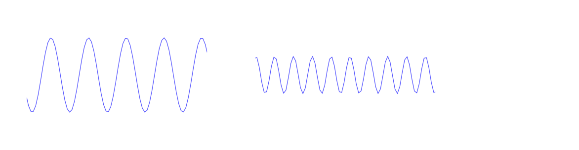
Two important properties of a wave are its height (called its amplitude) and its frequency, which is how far apart the peaks are spaced. The wave above on the left has a higher amplitude but lower frequency than the one on the right. Frequency is usually measured in Hertz, which is the number of peaks or cycles per second that will pass by. For wireless communications, usually we use Megahertz (MHz) or Gigahertz (GHz).
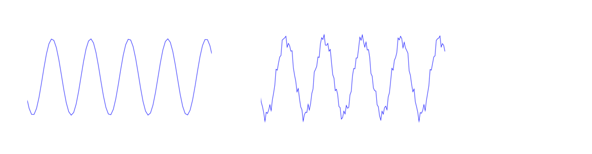
Waves can be used to carry information. The base wave is called a carrier wave, which is shown below on the left. The signal is carried by making small changes to the height of the carrier wave, like shown on the right. When we subtract out the carrier wave, what is left is the signal. This process is called amplitude modulation and it is the principle behind how AM radio works. A similar process called frequency modulation uses small changes in the frequency to carry information. This is the principle behind FM radio.
The EM spectrum starts with radio waves at the lowest frequencies, beyond radio waves come microwaves, then infrared, then visible light, then ultraviolet rays, then X-rays, and finally gamma rays at very high frequencies. Each of these can carry information as described above. The lower frequencies have less bandwidth and can't carry as much information. But they travel farther and can move through obstacles better than higher frequency rays. For instance, visible light has a very high bandwidth, but as we know it's blocked by all sorts of real-life objects, so it doesn't work well for wireless communication. However, fiber optics get around this by sending the light rays through a wire.
The sweet spot between distance and bandwidth is right in the upper radio wave and lower microwave ranges. These are frequencies from roughly 100 KHz to 100 GHz. Communications on these frequencies are highly regulated by governments because this range is so valuable. A lot of the range is reserved for things like radio and TV, as well as military communications. Each government has their own rules for these things. If you send a signal on an unauthorized frequency, you might get a visit from the FCC if your signal causes problems for people. Wi-Fi uses small frequency bands that are unregulated. They share that range with other things like baby monitors and garage door openers, so interference is a real problem for Wi-Fi.
Media Access Control
Media access control or (MAC) is about how several parties can all share the same medium. That MAC is the same one as in MAC addresses. If two parties both send signals down a wire or through the airwaves at the same time, then their signals can interfere with each other and you just get a garbled mess. It's a little like when a bunch of people in a room all start talking at once. MAC protocols are designed to control who has access to the medium to avoid this problem.
The main solution used in modern networking is carrier sense multiple access (CSMA). The basic idea is if you want to use a line (wire, airwaves, or whatever), you first check to see if the line is free. If it's not, then keep checking until it is free. Once you see it's open, then you can start transmitting. There are several problems with this.
- If both you and someone else are waiting to see if the line is free, then once it becomes free, you would both start using it at the same time and interfere with each other.
- Because of propagation delay, if a line is long enough, it might look like it's free to you, but in fact someone farther down the line might be using it and their stuff just hasn't made it to you yet.
- In wireless, there is the hidden node problem, which is pictured below. The circles indicate the range in which B and C's signals can be heard. Each can see A, but they can't see each other. So if B were transmitting, C would check and not see anything happening and would think it's okay to send things to A. But that transmission will interfere with C's once it gets near A.

You start by listening to see if the line is free. If it is, then you can start transmitting, but while you do, you listen to the line to see if there is anything else on the line that's not yours. If there is, then that's a collision. So you stop transmitting your data and send a jamming signal on the line. Other people transmitting will see that signal and know that a collision has taken place. If the line is really long, it's possible that someone could finish transmitting before the jamming signal reaches them, so to avoid this, Ethernet lines were limited in length.
Everybody then stops and waits a random amount of time before trying to transmit again. Initially, each randomly picks either 0, 1, 2, or 3 time units to wait. A time unit is a few microseconds. It's possible that two people pick the same random wait time and another collision happens. If this happens, then same process is repeated, but now the wait time could be 0, 1, 2, 3, 4, 5, 6, or 7 time units. If still another collision happens, then the random range is increased still further to 0 to 15 time units. It keeps doubling like this until a maximum range of 0 to 1023 time units. This process is called exponential backoff.
Ethernet
“Ethernet” is an old trade name. Ethernet has been formally standardized as IEEE 802.3, and you will occasionally hear people refer to Ethernet by that name. Ethernet was invented back in the 1970s at Xerox PARC, along with many other parts of modern computing like modern GUIs and laser printing. There were several other competing technologies over the years, some of which were better than Ethernet in a technological sense, but Ethernet was cheap and easy to use, so most wired networks now use it.
Ethernet has changed considerably over the years. Originally, it used a bus topology, where there was one long line of cable and computers were attached to it at regular intervals along the line. Everyone shared that same line. You could see everyone else's traffic if you wanted to, though you were only supposed to look at the traffic that had your own MAC address. In the 1980s people started to use the existing phone lines in buildings to build Ethernet networks. This was easier than running the special coax cable that the original Ethernet needed. In these new networks, it was hard to find where the wiring went bad if someone lost connectivity, so hubs started to be used. Here each computer would be wired into the hub, and you could wire hubs together. The topology associated with this is either a star topology for everyone connected to one hub or a tree topology. See the figure below for examples of what these topologies look like.

Here is how it works. When we first plug a device into a physical port on a switch, it doesn't know anything about that device. However, when that device first decides to send a packet out, the switch will observe the MAC address on that packet and record in a table that the device at that specific port has that particular MAC address. Then when packets come into the switch, it looks at its table and knows which port to send things out on. Note that the ports are not the same ports as in layer 4. These are actual physical places where an Ethernet cable gets plugged into.
Using switches now means collisions are no longer a problem. We don't need to use CSMA/CD or anything else. In the old bus topology everyone all shared the same line. Now, each device is plugged into a switch at its own port. It never sees any of the other devices (or their traffic). The terminology used is collision domain. In the bus topology, everyone was on the same collision domain. Now everyone is in different collision domains because the switches keep everything separate. Switches started to become widely used in the 2000s. Before that, they were too expensive. They are still expensive, but not as bad as they used to be.
The first part of the ethernet header is a preamble. This is an alternating sequence of 62 0s and 1s, followed by two 1s. The purpose of this is to help the sender and receiver synchronize their clocks. Data is sent very quickly, with millions or billions of bits a second, so the sender and receiver need to be in sync or else they won't understand each other. This alternating sequence helps with that. The last two bits are 1 to indicate that the preamble is over.
Following the preamble are the destination and source addresses, which are both 48 bits. After that is a type/length field whose meaning has varied over the years. It either indicates the length of the message or what type of Layer 3 traffic it is carrying.
The data comes next. There can be up to 1500 bytes of data. Padding is there in case the message is too short. If a frame is too short, then it's possible that if there's a collision, the sender could be done sending before the jamming signal reaches them and not realize that a collision happened. The last part of the header is a checksum. It serves a similar purpose to the checksums at higher layers, but it uses a different type of checksum called CRC-32 (CRC stands for cyclic redundancy check).
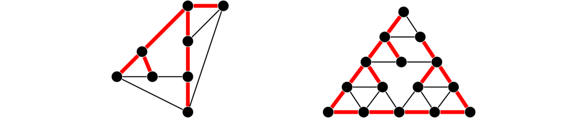
The Spanning Tree Protocol (STP) is used to avoid routing loops in a network. A routing loop is where packets get bounced back and forth between the same few routers continuously, such as a packet getting forwarded from A to B to C to A to B to C to A ….A spanning tree in a graph is a subset of the vertices and edges that includes all the vertices (spanning) and contains no cycles (is a tree). We want it to be spanning so that everyone can reach everyone else, and we want it to have no cycles so that routing loops can't happen. In STP, routers talk to each other in a similar way to what they do in RIP, telling other routers information about what they are connected to. Everyone uses this info to build a spanning tree basically by “turning off” specific edges by agreeing not to use them to send data. See below for some graphs with spanning trees highlighted.
Error detection and correction
Errors in transmission can be pretty common, especially at the lower layers, so it's important to have a way of catching them. Error detection is typically done with checksums. Here is an example to demonstrate the idea. Assume the data being sent is in binary. We add up all the 1s, and our checksum is 0 if there are an even number of 1s, and 1 if there are an odd number of 1s. This type of checksum is called a parity bit. The sender computes this checksum and sends it along with the data to the receiver. When the receiver gets the data, they compute the checksum on the data and see if they get the same checksum as what the sender sent. If they are different, then we know there was an error. For example, suppose we have the situation below. Notice that a bit gets flipped in the transmission. The checksum catches it because the number of 1s goes from odd to even.
| data | parity bit | |
| what the sender sends | 01100001101 | 1 |
| what was actually received | 01100101101 | 0 |
A better checksum is CRC-32. It catches all burst errors up to 31 bits in length. Burst errors are a common type of error where things get messed up for a bunch of bits in a row. CRC-32 also catches many types of transposition errors. The math behind CRC-32 is a little more complicated than we can get into here, as it involves material from an upper-level undergraduate course in abstract algebra. CRC-32 is fast to compute and is 4 bytes in size. Since devices can often get millions of frames in a second, we want it to be very fast, and since the checksum is attached to every frame, we don't want it to take up too much space.
Error detection just tells you if an error happens. After that, the frame will have to be resent. A related technique called error correction allows us to correct errors without having to resend a frame. Techniques like Hamming codes are often used for this. Just like a checksum requires us to send some extra data to check for errors, error correction requires us to send even more data. This can be enough to cut down on the efficiency of the line, so error correction is used in situations where errors are common, like in wireless communications. Error detection is used when errors are not very common, like in Ethernet. There's a cost-benefit analysis that needs to be done to determine if the extra data needed for error correction averages out to be more or less than the extra work needed to resend lost frames.
Wi-Fi
Wi-Fi is a trade name for a wireless communications system that we're all familiar with. People often refer to it by IEEE 802.11, which is the name of the set of standards that define Wi-Fi. The original standards were 802.11a and 802.11b. Various new standards have been introduced, the most important of which are 802.11g, 802.11n, 802.11ac, and the new 802.11ax. Each new standard generally provides faster data rates due to improvements in technology.
The 2.4 GHz band has channels 1 to 14, though not all channels are available in all countries. Channels 1–11 are available in the U.S., and 12 and 13 are available only in low power mode. Channel 1 is specifically at frequency 2.412 GHz, channel 2 is 2.417 GHz, and each goes up by .005 GHz from there. Nearby channels interfere with each other, so if you're running a Wi-Fi network, you wouldn't want it to use both channels 1 and 2 or 1 and 3, for instance. Channels that are 5 or more apart don't interfere much with each other. For this reason, channels 1, 6, and 11 are commonly used, and the others not so much.
The 5 GHz band has a wider variety of channels. They are 36 in the range from 36 to 64, 100 to 140, and 149 to 165, going up by fours (so 36, 40, 44, etc.).
Usually a Wi-Fi network has an access point (AP), which everyone on the network communicates with. That AP is usually connected to a wired network. When devices connect to the AP the process is called associating. The AP sends out beacon frames every tenth of a second or so. This contains info like the network's data rate, the type of security, the AP's MAC address, and the AP's SSID. The beacon frame is basically the AP announcing itself so that others know it's there.
Related to beacons are probe requests. These are sent out by computers and phones looking for networks they've previously been connected to. This is how your device will automatically connect to a network it knows once it's in range. The problem with this is that your device is constantly broadcasting the names of all the networks it has previously been connected to. These broadcasts can be picked up pretty easily, say by running Wireshark in monitor mode. Chances are the list of networks your phone has been connected to is unique to you. So if someone knows this, they can use this to know when you're nearby, and they can also use this to see where you've been since the SSIDs often are pretty descriptive.
Wi-Fi has a number of other management frames besides beacons and probe requests. One of the most interesting is the deauthentication frame, which is used when an AP wants to boot you from a network. The problem is that these can be easily spoofed. That is, someone can construct a deauthentication frame to make it look like it came from the AP, and they can use that to boot people off of a network.
Odds and ends
When the internet was first being developed, there was a debate as to whether it should be a circuit-switched or a packet-switched network. The phone system at the time was circuit-switched. When you made a call, there was a direct line that ran from your phone to the phone company office. There an operator or a switching system would patch some cables together and the connection would then run from the phone company office over to the other person on the call. So there was a continuous line that connected you two, and that was your line for the duration of the call. No one else would use it.
In packet switching, everyone shares the same line. They break their communications into chunks of information called packets, and everyone would put their packets on the line. Header information such as addresses and port numbers would be used to help tell whose traffic was whose and how it should all be forwarded to their destinations.
Packet switching won out over circuit switching, and it's hard to imagine how today's internet could exist in a circuit-switched network considering the trillions of connections that happen daily.
Multiplexing is a networking concept that generally is about multiple things being carried all over the same line at once. At layers 1 and 2, there are a few ways this can work.
- Time division mutiplexing (TDM) — This is where everyone wanting to use the line takes turns. During those turns, they get the full use of the line. For instance, maybe A gets the line from time 0 to .1, then B gets it from .1 to .2, then C gets it from .2 to .3, then A gets it again from .3 to .4, etc.
- Frequency division multiplexing (FDM) — This is where everyone sends their stuff on different frequencies. An example is radio, where the Mount's radio station is at 89.9 MHz, Gettysburg College's station is at 91.1 MHz, etc. Another example is on fiber optic lines. Different frequencies of light correspond to different colors. So it would be a little like person A getting to use the red band, person B getting to use the blue band, etc., though in practice it's more complicated than that.
- Code division multiple access (CDMA) — In this, each person gets their own random sequence called a chipping code. We take the exclusive or (XOR or ⊕ ) of the signal with the chipping code. The XOR operation is defined such that 1 ⊕ 1 = 0, 0 ⊕ 0 = 0, 0 ⊕ 1 = 1, and 1 ⊕ 0 = 1. Basically, it's 1 if the two things being XOR-ed are equal and 0 if they are different. XOR-ing the chipping signal in a second time will undo the first XOR and give the signal. We use the different chipping codes to tell the different signals apart. CDMA is used in 3G phone networks.
Tanenbaum's and Wetherall's excellent book Computer Networking has a nice analogy for all this to a room full of people talking. TDM is where everyone takes turns talking. FDM is where everyone talks at different pitches. CDMA is where everyone talks in a different language.
Converting data to signals
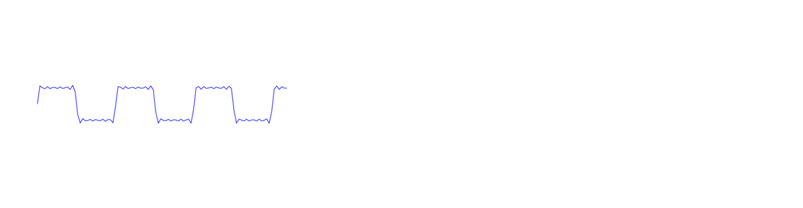
The 0s and 1s of digital data need to be converted into electrical impulses in order to physically send the data. This is the job of your network adapter. One way of doing this is to consider a data value of 0 as a low voltage on the line and 1 as high voltage, like pictured below. The high spots correspond to 0s and the low spots to 1s. We've shown things a little fuzzy like this to indicate that electrical signals will not be perfect.
There are a couple of difficulties we run into with this system:
- How will we distinguish between a run of say five 0s in a row versus a run of six 0s? The solution is to use a clock.
- How will we know what a high voltage is and what a low voltage is? When we're communicating with someone far away, their signal will be weaker than someone nearby. To distinguish things, the system maintains a running average of what it's seen over time to help it distinguish between low and high.
A lot of real data has long runs of 0s and 1s. Often this happens randomly, but it can also happen due to the patterns in the data. For instance, a large black area in an image might translate to a long run of 0s. These long runs can mess with both of the things described above. During a long run, the clocks of the sender and receiver can get out of sync. And a long run of 0s or 1s will skew the running average, making it harder to tell what voltages are low and high. So we need to do something to prevent long runs of 0s and 1s. There are a few different approaches.
| data | 00 | 11 | 11 | 11 | 11 | 00 | 00 | 00 | 00 | 11 | 00 |
| clock | 01 | 01 | 01 | 01 | 01 | 01 | 01 | 01 | 01 | 01 | 01 |
| output | 01 | 10 | 10 | 10 | 10 | 01 | 01 | 01 | 01 | 10 | 01 |
There are 16 possible 4-bit strings, namely 0000, 0001, 0010, …, 1111. And there are 32 possible 5-bit strings. 4B/5B encoding replaces each 4-bit string with a carefully chosen 5-bit string. These strings are chosen so that they never start with more than one 0 and never end with more than two 0s. This means that if you put two of them side-by-side, you will never get more than three 0s in a row. Here are a few of the replacements:
| 4B | 5B |
| 0000 | 11110 |
| 0001 | 01001 |
| 0010 | 10100 |
| 0011 | 10101 |
| 0100 | 01010 |
| ··· | ··· |
| 1111 | 11101 |
A few link layer details
- Have the sender specify at the beginning of the frame how much stuff they are sending.
- Use special flag bits or bytes to indicate the start and end of a frame. One issue with this is that those bits or bytes might naturally occur in the data. To deal with this, we can “escape” those bits or bytes by preceding them with a special sequence of bits or bytes. This is like in programming languages, when you want to put a quote character inside a string. Since the quote indicates the end of a string, we have to be careful. The solution is to escape it with
\"as in"He said \"Hi!\" to me". The escape sequence itself might also come up naturally in the data, so we might have to escape the escape sequence in that case. In programming languages, this is similar to using\\to escape the\escape character.
- Stop-and-Wait — In this scheme, the sender sends a frame and then waits to send anything else until it receives an ACK from the receiver. If no ACK comes after a certain amount of time, the packet is resent. This is simple, but not very efficient since the sender can't send more than one frame at a time.
- Go-Back-N — This is a sliding window system that is a lot like TCP's sliding window system.
- Selective repeat — This is very similar to TCP's selective ACKs (SACK), where a receiver can specify which frames were received and which ones were not.